Author Archives: admin

CX500 Valve Job

Below are the details and pictures put together by Eric while doing a valve/head clean on a CX500 EuroSport. It is exactly the same job for all the CX models.
Thanks Eric for putting this together.

Finally got to finish re-grinding the valve seats on the CX500 Project engine. I had done the Right Hand Side (RHS) already and just had to finish the LHS.

So first things first – remove the sparkplugs and make sure the cylinder is at TDC (Top Dead Center) – this is mainly to ensure there is no load on the push rods – you should be able to feel a little bit of play/movement in all four rocker arms if you pull and push them. So check flywheel

1

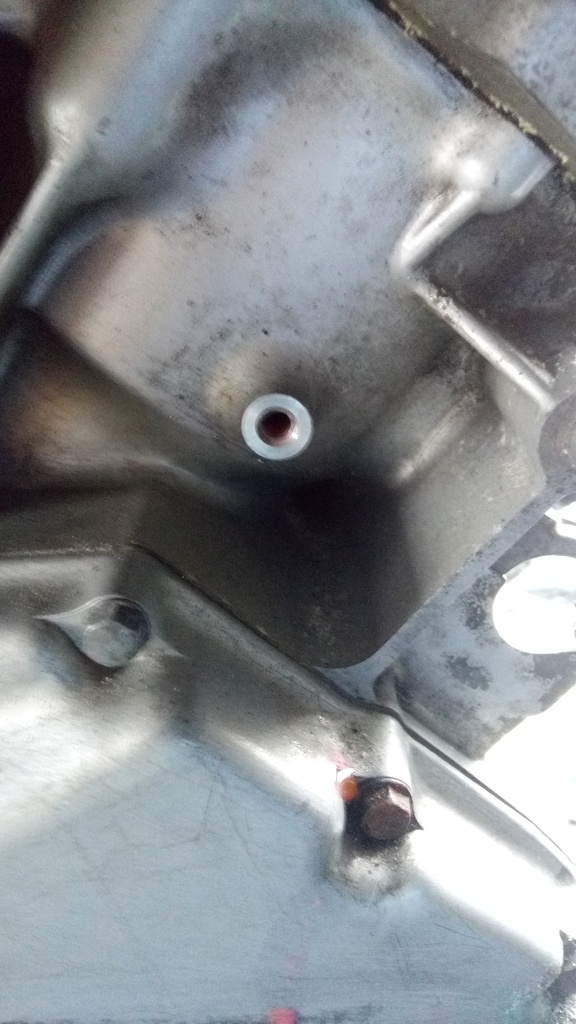
Dont forget to open the coolant cylinder drain screw and allow coolant to drain from around cylinder – if you dont do this then once you slacken off the head bolts then coolant will start to leak from around the head gasket – ask me how i know this ??

IMG_20160220_143034_zpshxhdj2sv

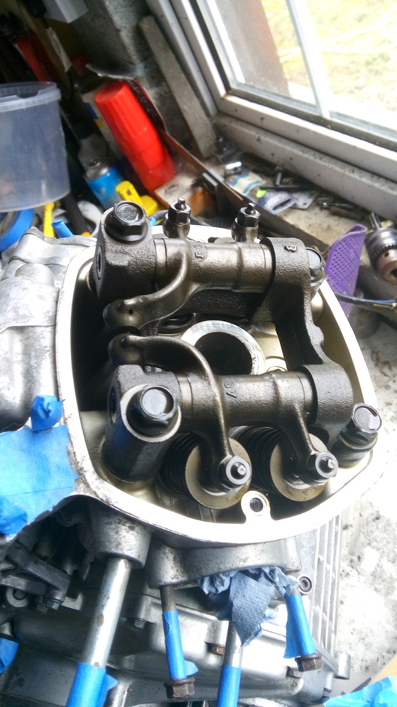
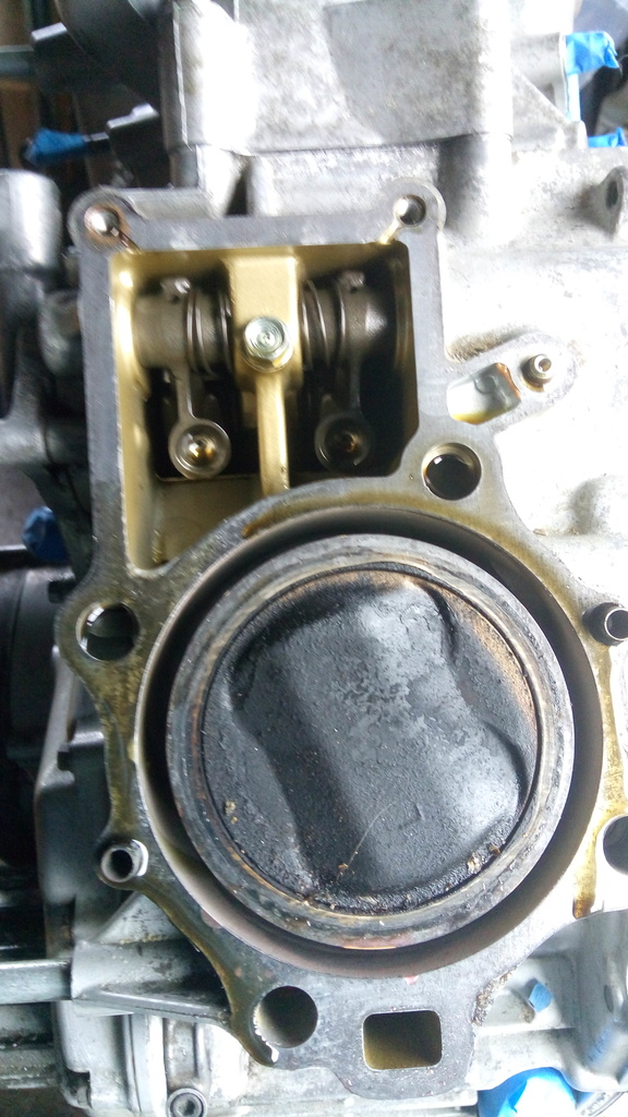
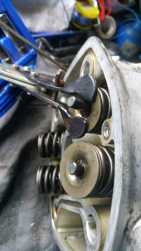
Remove the rocker cover and here’s what you have …………

IMG_20160220_142215_zpsijy9zl4e

Gradually loosen the 4 headbolts – do this in a criss-cross pattern, a quarter turn at a time initially.

IMG_20160220_142524_zpsdnfc7m3u

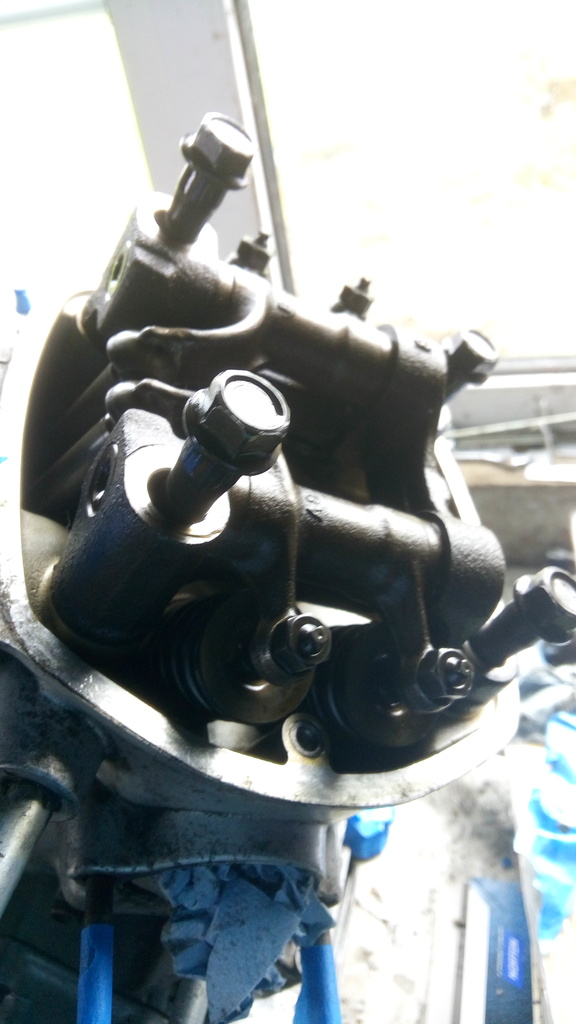
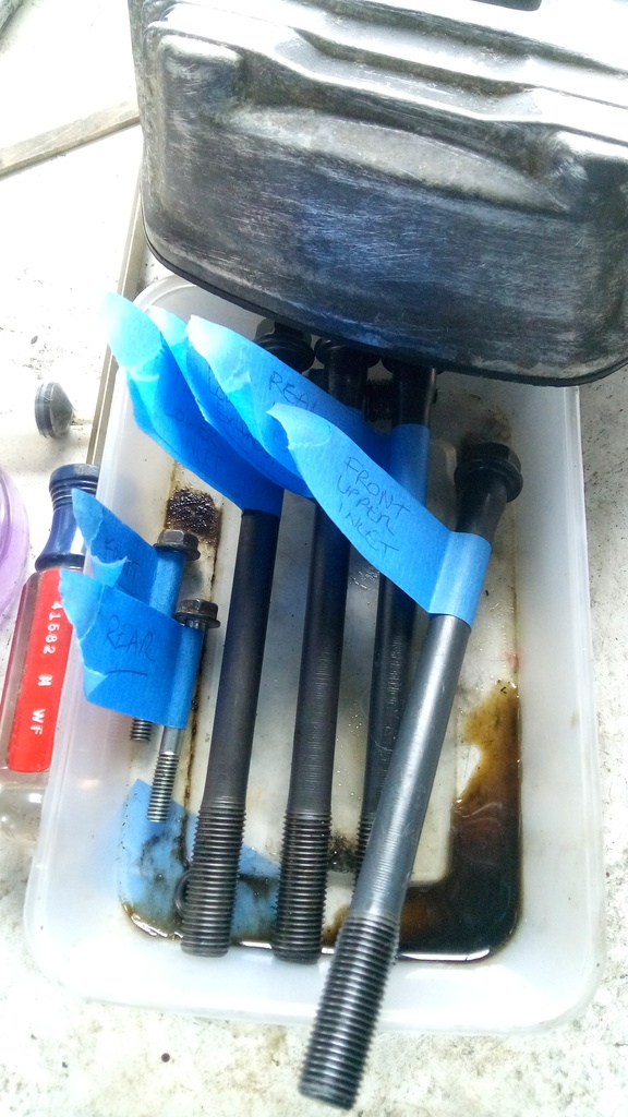
Remove the bolts one at a time and label them for future reference. Remove the 2 x 10mm bolts on the top of the head.
Guru Note – the threads on these bolts look like new. Most time they are very dirty. Ensure you clean them thoroughly before you put these bolts back into the engine.

IMG_20160220_143419_zpsouupjpiw

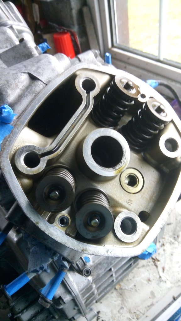
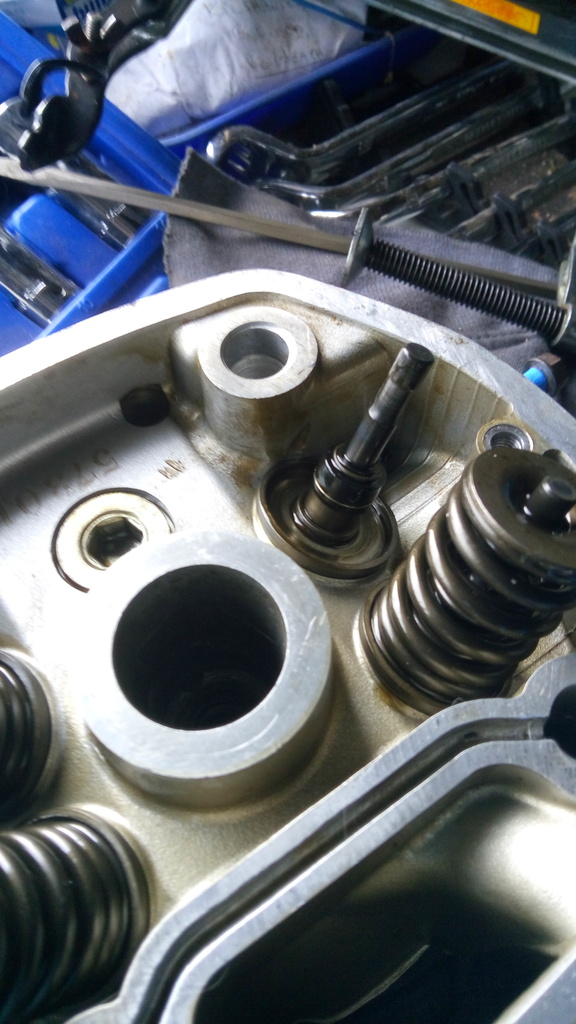
And here’s what you’re left with after lifting off the rocker assembly

IMG_20160220_143750_zpsn7mkulz7

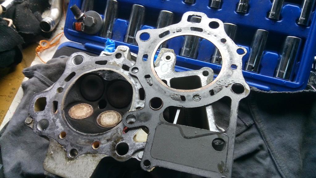
A few gentle taps around the edge with a rubber mallet should loosen the head and allow you to lift it off – in this case the old gasket stuck to the head – I prefer this to it sticking to the crankcase where it seems to be harder to remove.

IMG_20160220_143920_zpsnkqv0mpt

IMG_20160220_143928_zpsagluohbd

And in this case the old gasket lifted off easily in one piece.
Guru Note: If it does not lift off easily you will have to very carefully scrape it off piece by piece – patience is the order of the day.

IMG_20160220_144609_zpsel9kskja

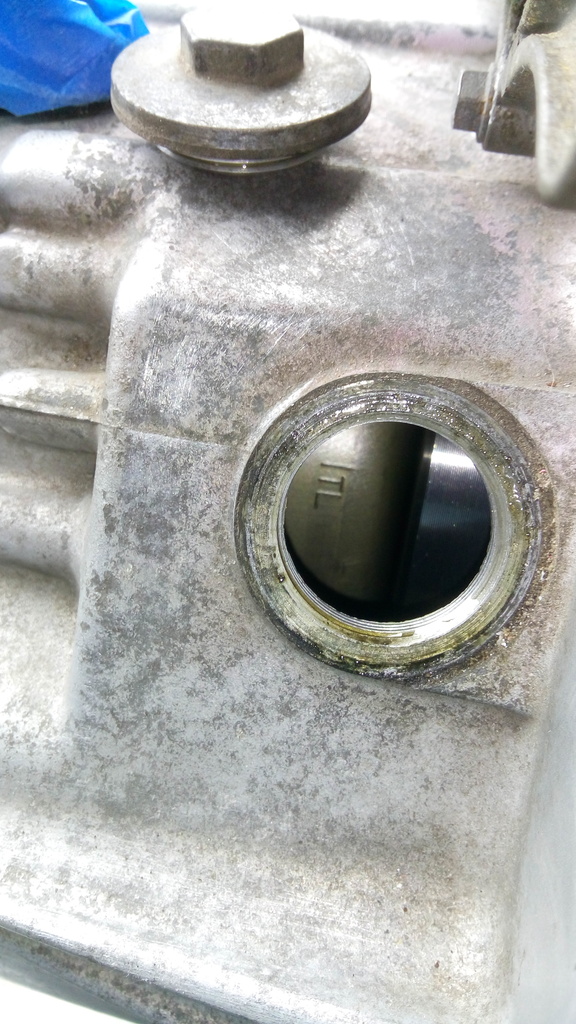
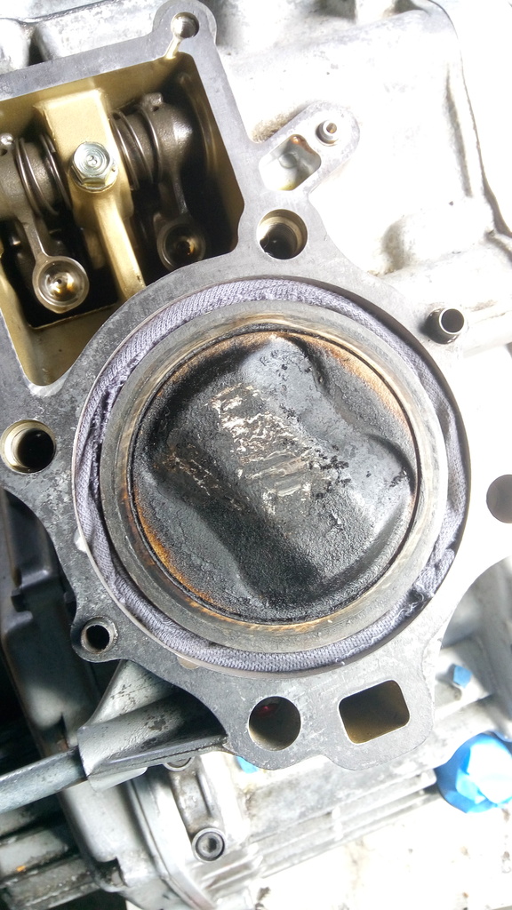
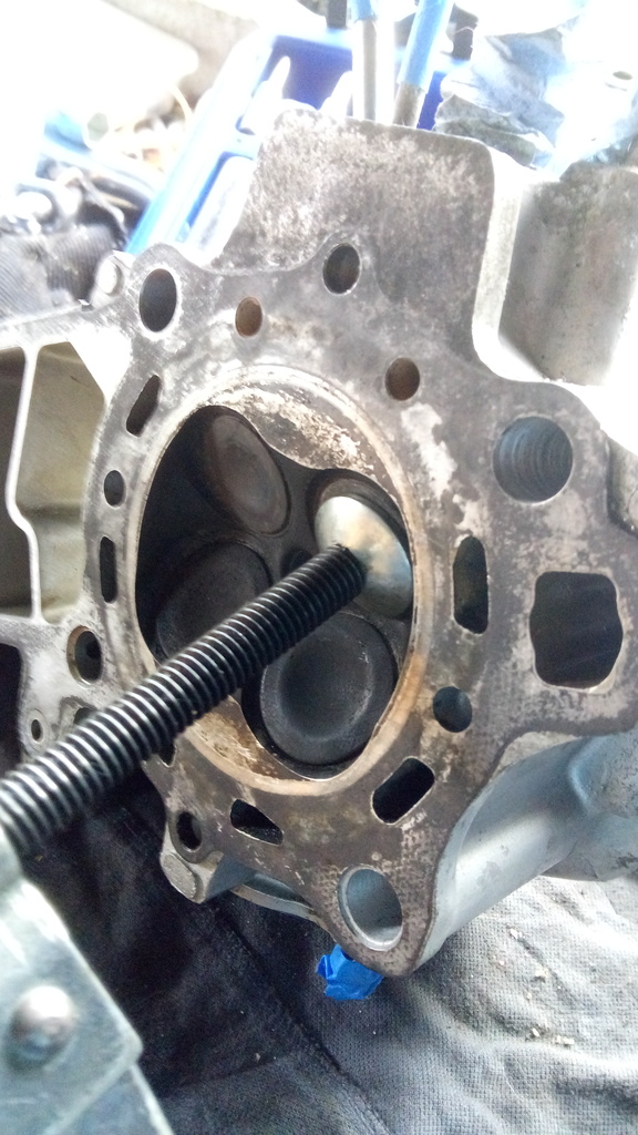
I stuffed some rag down the coolant gap to stop dirt etc. getting in here when I was cleaning off the top of the piston etc

IMG_20160220_144448_zpsd9olhyej

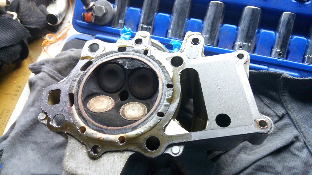
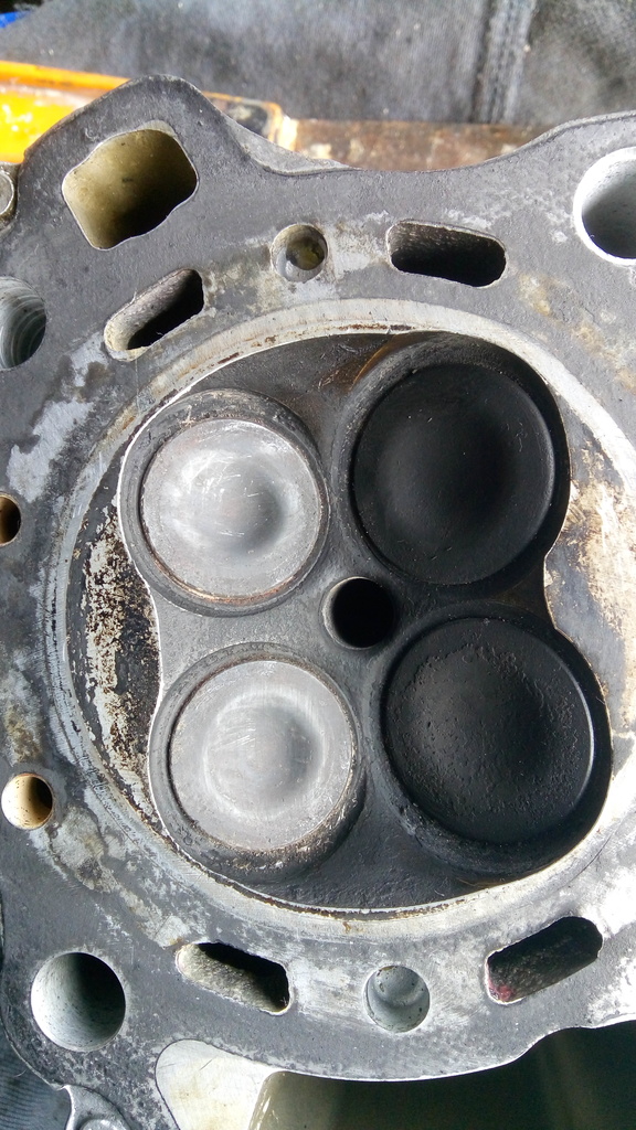
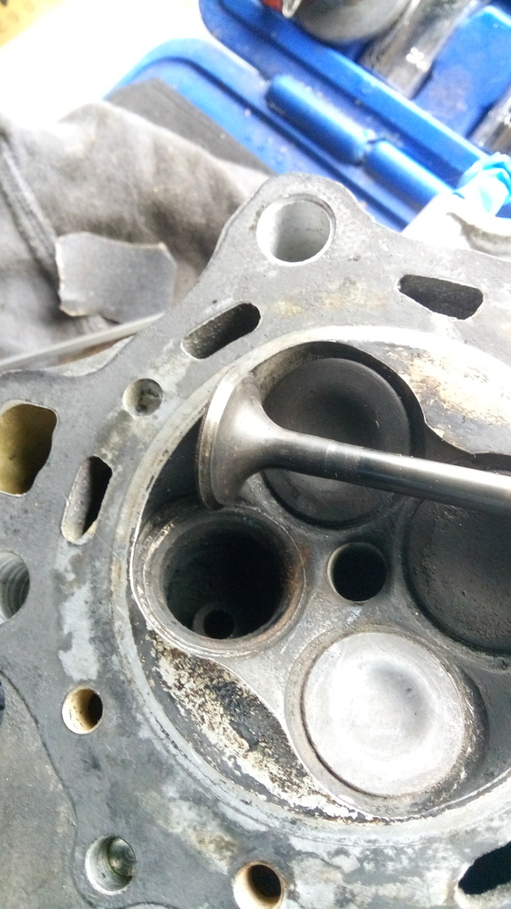
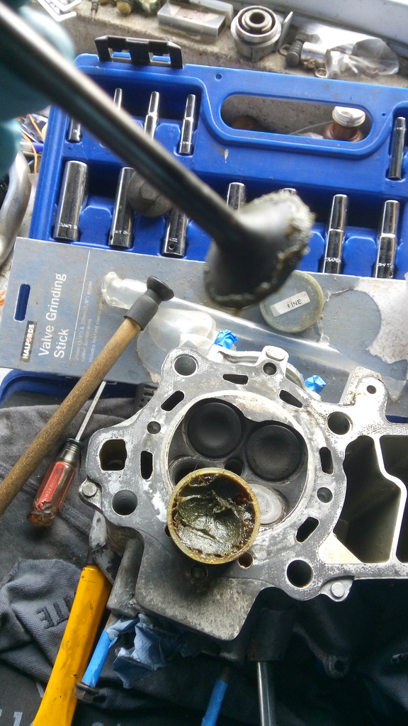
Spot the exhaust valves with the carbon deposit on them – I usually scrape the majority of this off with a flat screwdriver before I remove the valves from the head.

IMG_20160220_144655_zpsfjrxqwzx

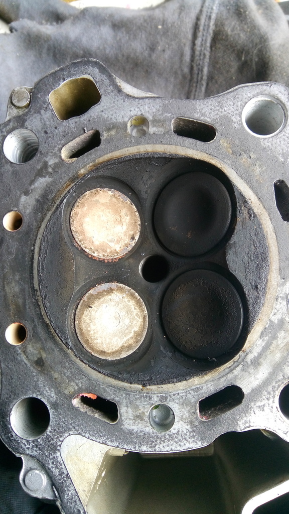
Most of the gunk gone below – when I take the valves out I will clean the inside of the head further – avoiding the seat of course.

IMG_20160220_145336_zpsandgll9g

I have a valve tool for removing valves (I don’t know how you could do it without one !!) – theres the side that sits on the valve head

IMG_20160220_145608_zps7o7mloia

The spring/collet end

IMG_20160220_145617_zpsjn0pmyxi

And here’s the whole tool – when placing this make sure you take into account the slope of the valves and place in the correct way round so you’re pressing in a straight line in the direction of the valve travel. (Along the axis of the valve).
Guru Note: You can make one of these valve compressors as well. Look on the internet there are lots of ideas.

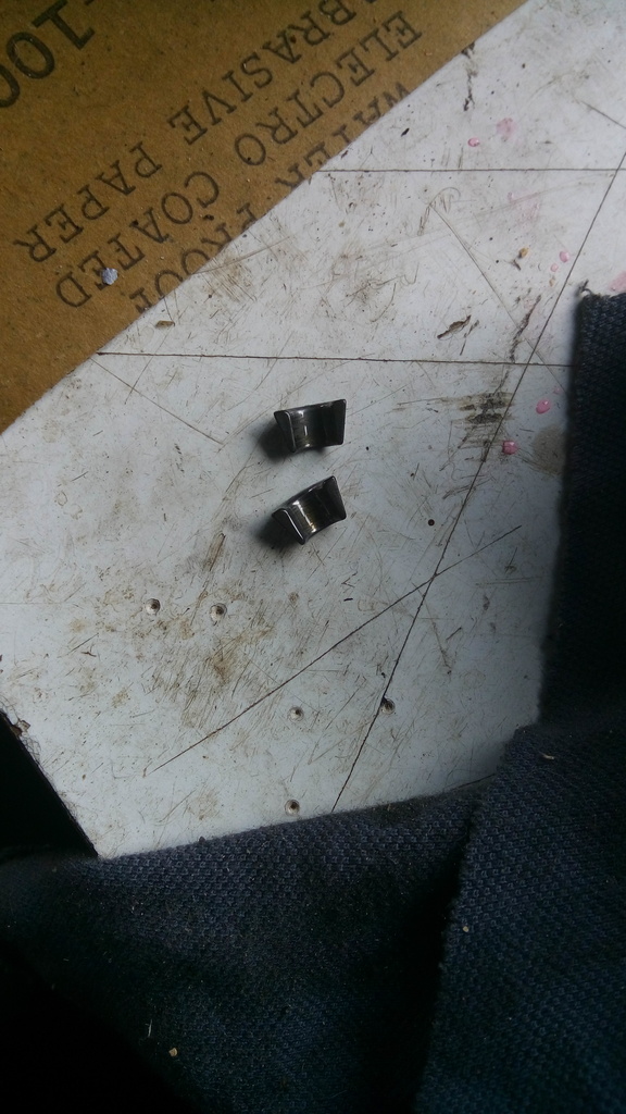
Here’s the little puppies (collets) that you’re trying to remove – they’re small and will fall out once you release tension on the valve – dont lose them.
Guru Note: Not only will they fall out, but they will grow tiny legs and sprint away into the mist never to be found again. Try having the head turned upright with the collets on the top. They can be easily removed then with a magnet or magnetic screwdriver.

IMG_20160220_145752_zpsasf7esmh

And here’s where they came from – around the top of the valve stem.

IMG_20160220_145802_zps5iea0qvw

Pull the valve out – pry off the valve stem seal and remove the valve spring seat (if you dont it will fall off later and the garage gremlins will get it !!)

IMG_20160220_150137_zps0v1dqywr

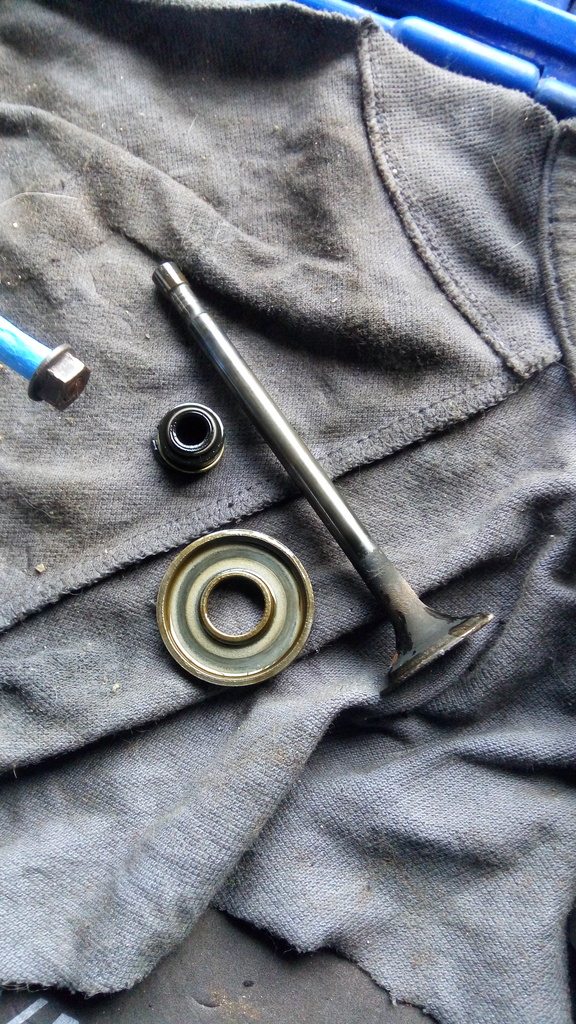
This is the old valve stem seal still in place. You will destroy these in getting them off, they are going in the bin anyway.

IMG_20160220_145953_zps6ze9evit

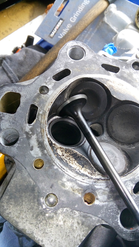
Below I was trying to show the old valve seat ……not a nice even grey colour, some small black spots on it…. will need grinding.

IMG_20160220_151003_zps17dtbj8b

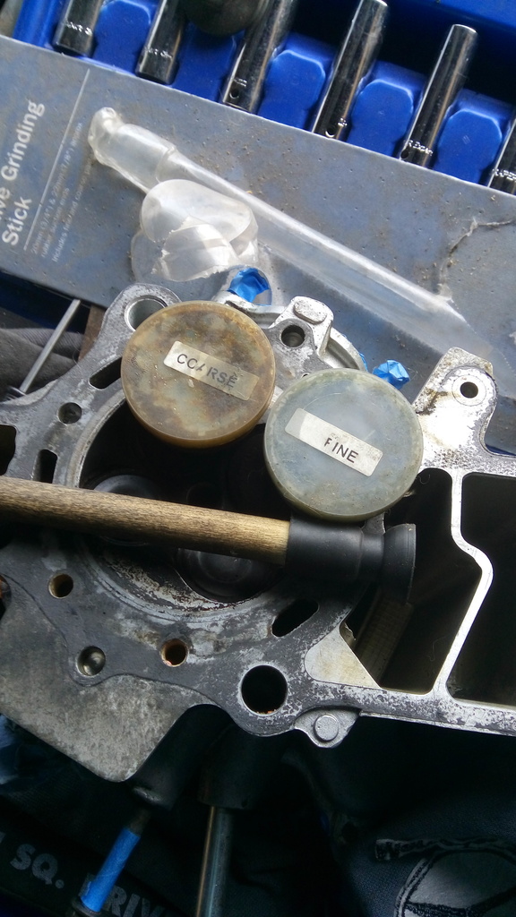
Valve seat grinding kit (got in halfords years ago) – a coarse and fine grit as well as rubber tipped stick.

IMG_20160220_151140_zpsawshvgu8

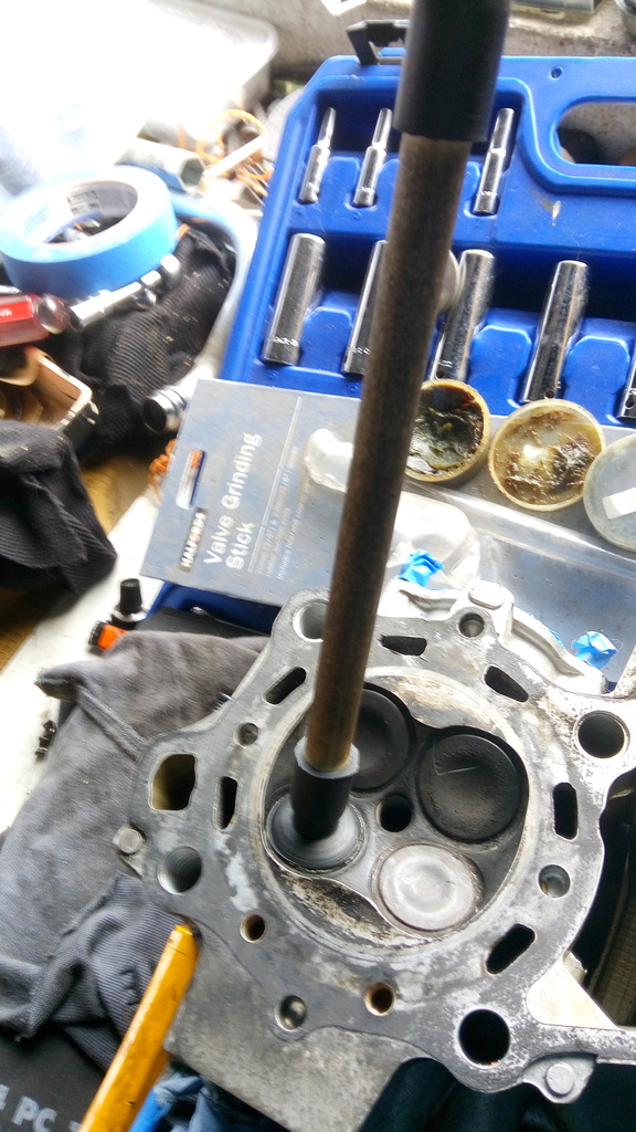
Hard to get a good photo here – this is some of the coarse grit on the narrow face of the valve – you only need a little bit – you only put it on the valve, not the head. Then slide the valve back into its guide so it sits roughly the way it was.

IMG_20160220_151444_zpszfhpsmnk

Attach the rubber sucker stick to the flat head of the valve. Then like you were trying to start a fire rub it back and forth between your palms for 5 or 6 seconds – lift it about 1cm, turn it 90 degrees, drop it and “fire-start” again for another 5 or 6 seconds. Do this about 10 times or so – then remove the valve from the head, wipe off the grit/paste from both the valve and the head.
Guru Note: Make sure you get 100% or more of the paste off the valve and seat. Use petrol or carb cleaner or whatever you can lay your hands on. It is very important to remove all the paste.

IMG_20160220_151734_zpsosls2du0

Hopefully you’ll only need maybe one run with coarse paste and another with fine paste – unless you notice marks on the valve seat that dont seem to go away – what you’re looking for is a nice even dull grey band where its nice and even – black marks would indicate its not smooth etc and would need to be re-done.

IMG_20160220_152443_zpsnjtwxpyr

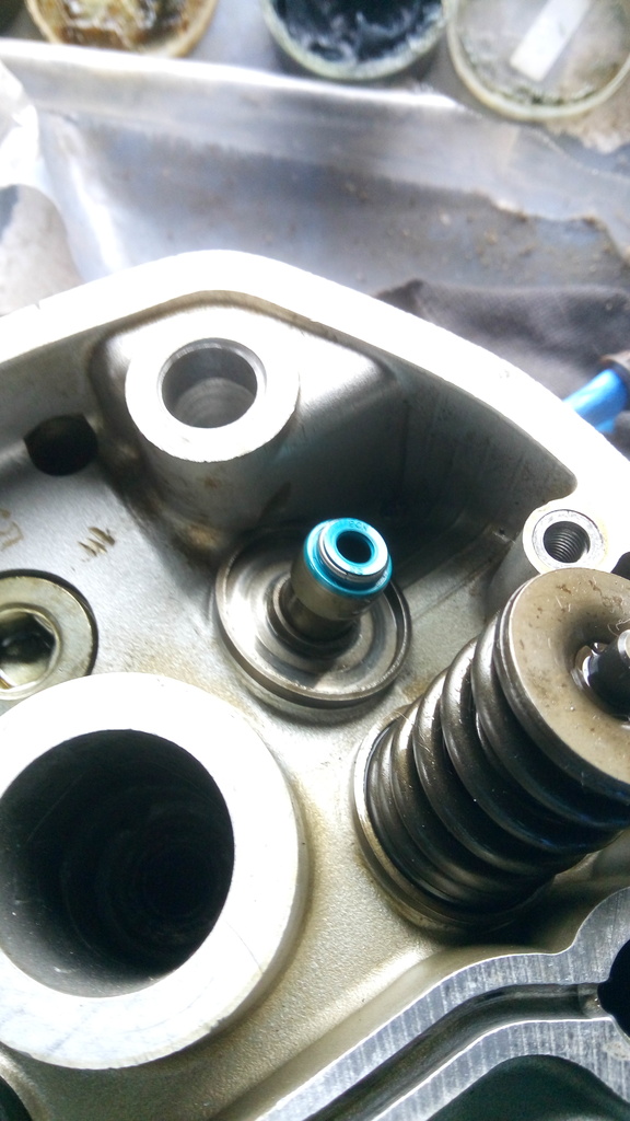
Then its time to refit the valve spring seat – DONT FORGET THIS – if you fit the valve stem seal before this then this wont fit over the seal and you’ll have to ruin the seal taking it off again (dont ask how I know this) – THEN fit the valve stem seal – make sure if down snug.
Guru Note: How do you know this ??
Guru Note: You will notice Eric is using a blue valve seal, usually made from modern Viton or Silicone rubber. These seals are much better than the originals or the ones in the spurious gasket sets.

IMG_20160220_152634_zpsmzyqwadx

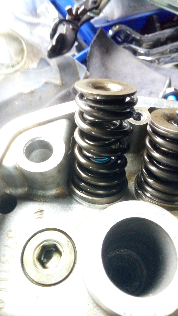
Fit the springs back in place – I always fit the springs back the way I took them off – I believe there is a documented spring length in order to test the springs are within tolerance – I havent found one yet that wasnt !!
Guru Note: Liberally cover everything you reassemble with clean engine oil.

IMG_20160220_152703_zpsn35hk4em

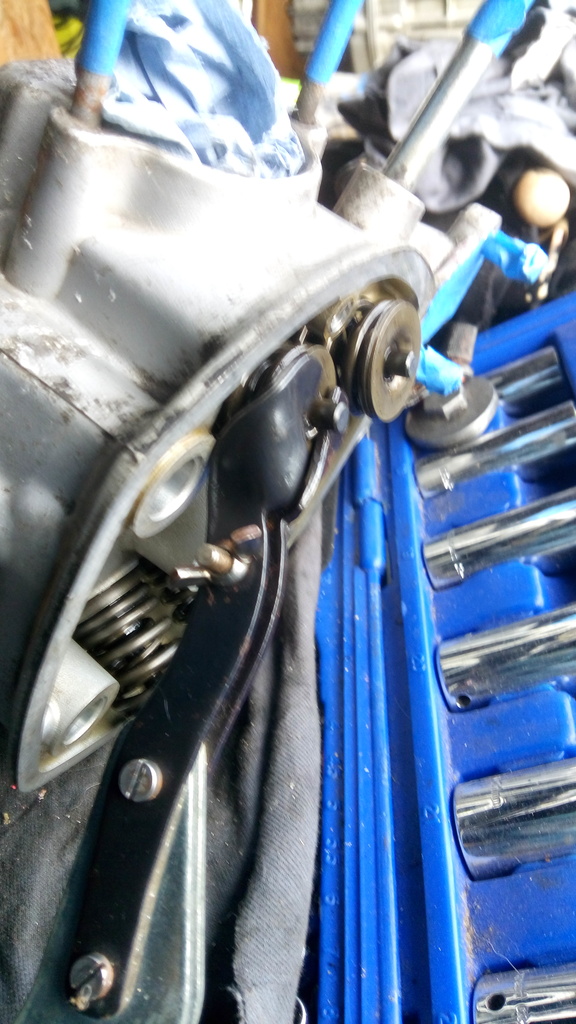
Then fit the valve compressor tool – this is fun as you have to have 3 hands here to hold the spring from falling off – hold the valve – turn the head sideways and fit the tool…and tighten it a bit…….what fun.

IMG_20160220_152933_zpsp0zcaazy

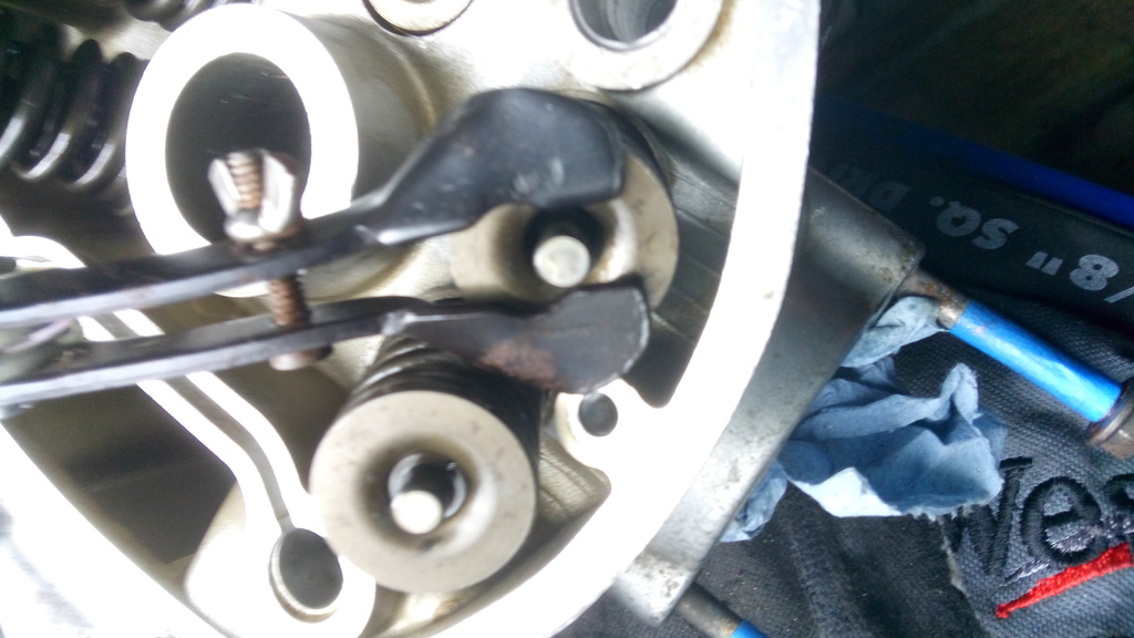
When the tool is in place – tighten it to compress the spring and make a space to drop in the little collets (THAT YOU DIDNT LOSE !!)

IMG_20160220_152948_zpsf5tlnamb

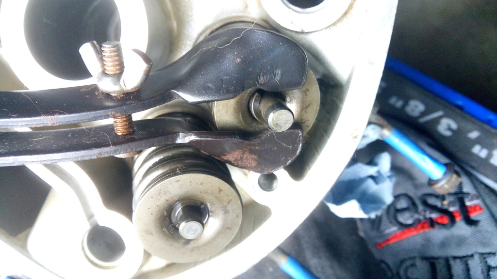
Then slowly loosen the valve tool to allow the collets bed in. Remove the spring compression tool.

I always test each valve – I use the tip of the handle on a rubber mallet and press (very hard) on the tip of the valve a few times to ensure it opens and closes and everything is ok.

Then its a simple case of repeating this for each of the other 3 valves. I clean the piston head a bit before removing the packing I put in the coolant gap. I give head surfaces a little wipe down with 800 grip sandpaper and wipe the surfaces with meth spirits.

Fit a new head gasket (i dont mess with any but genuine Honda ones). Dont forget to fit a new little oil-jet rubber o-ring.

Fit the head carefully ensuring the o-ring or nothing moves.

I screw in the 2 x 10mm bolts hand tight.

Fit the rocker assembly.

Install the push rods – I put them back in the way they were and in the position they were in.

I put the head bolts back where they came from – tighten them with fingertips (difficult as some of them have oil in the bottom and need a spanner).

Tighten in a criss-cross pattern until snug – then get out the torque wrench to finish them off, about a quarter turn at a time in a criss-cross pattern until each click at about 38 to 40ftlb.

Pinch up the 2 x 10mm bolts tight.

Squirt clean engine oil on the rocker assembly and valve springs.

I then usually turn over the engine by hand using the front nut on the engine a few times then go back and check the valve gaps etc.

job done !

Eric.

Everything about wiring

Blatantly robbed from the internet. Posted up here for all to use and reference.

Reg in Bristol is credited with allot of this knowledge and rightly so.

Color of Wires and where they go
For the most part its quite easy really Honda use the same colour conventions on all their bikes. So if you say find a green/blue wire on an 82 GL1100 you know its the cable between the temp sender and the gauge and any green wire is ground
‘for the most part’
its in the minor differences where routing and description helps ie the supply to the flasher relay black early CX models usually CDU ones white/green later usually TI models GLs Eurosports etc
Without routing and descriptions/notes its of limited use and may not achieve its intended goal of demystifying the wiring. I’d use a format like main colour – tracer if any – from -to

• Green:
from/to: various Notes: Ground wires on all systems, all green wires should have continuity (ie zero or very low resistance) to each other the frame and the battery negative terminal.

• Green/Blue
From: temp gauge To: temp sender in thermostat Notes: can be disconnected near thermostat and the voltage read with igntion on to check for good 7V supply if the regulator is suspect.

• Blue/Red
From: Oil warning light To: Oil pressure switch on front of engine Notes: May also be found under ths seat on early US spec bikes with rear light failure units aka ‘stop warning unit’ Has been known to cause alarm and confusion with no oil pressure. Often disconnected because of this.

• Black
From: Ignition switch To: Various Notes: With ignition on, black wires supply the fuse box and various systems and multiple wires are tapped from the main harness.

• Black/White
READ THIS FIRST !! Overview: This colour cable has two very different uses depending on the type of ignition used so care must be taken and the details understood to avoid damage. Be aware the kill switches work differently between CDI/Ignitech and TI bikes.
CDI: From CDI box or ignitech To: Kill switch Notes: The kill switch (closed)shorts this to ground in order to stop the engine In standard bikes it shorts stator source coil output to ground. On Ignitechs it pulls a signal wire low which stops the output.
TI: From: Kill switch To: coils and spark units Notes: This cable supplies power to the ignition system from the kill switch with the switch off(open),the supply is interrupted

• Red
From: Main fuse To: Ignition switch Notes: Supplies power to the bikes electrical systems

• White/Green
From: 4 way Fuse box To: Flasher relay, Brake lamp switches, Clutch switch, Horn switch, Pass switch (UK models) Notes: used on later bikes with a 4 way fuse box to supply the above systems

• Red/White
From: Regulator rectifier (RR) To: main fuse. Notes: carries all DC power from the RR May terminate at the battery side terminal on the solenoid and a red cable may be used from there to the main fuse. Some wiring diagrams, Haynes for instance, have errors showing how this is actually routed and connected.

• Grey
From: flasher relay To: flasher selector switch on LH bars Notes: flasher relay may be supplied by a Black cable on early bikes or a White/green on later bikes

• Light blue
From: flasher selector switch on bars To: Rh flashers front, rear and panel

• Orange
From: Flasher selector switch on bars To: LH flashers front, rear and panel

• Light Blue/White
From: Flasher selector switch To: RH front flasher Notes Front running lights on some US spec models

• Orange/White
From: Flasher selector switch To: LH front flasher Notes: Front running lights on some US spec models

• Yellow/Red
From Starter button To: Solenoid coil Notes: Supplies power to the solenoid coil when button pressed the solenoid when actuated, passes power from the battery Live terminal to the starter motor

• Dark Green/Red
From: Solenoid To: Clutch switch and blocking diode Notes: See starter system diagram on wiki for full explanation Briefly, the solenoid can only actuate when either the neutral switch or clutch switch is closed. The diode is only there to prevent the neutral light glowing when the clutch is pulled to make gear changes
File:Starting
starting diagram with diode.jpg


• Light Green/Red
From: Neutral indicator To: Neutral switch on rear of engine and blocking diode Notes: See starter system diagram on wiki for full explanation Briefly, the solenoid can only actuate when either the neutral switch or clutch switch is closed. The diode is only there to prevent the neutral light glowing when the clutch is pulled to make gear changes


• Notes on running lights:
The Haynes manual shows some models with all black wires at the flashers and front running lights These may be short stubs at the light assemblies or an unclear diagram Careful inspection advised.
Bikes with running lights have a more complex flasher selector switch and use double filament bulbs in the front. The power to a running light is cut when the flasher for that side is selected. Its been known for some folk to confuse the running light with the flasher when fault finding.
Here is the colour code as an image that you can download & print (from Sidecar Bob)

#Honda_Wire_Color_Codes

CX 650 Custom Build Part 2

The 650 engine has a longer stroke than the 500. This means the top hanger bolt is a bit further up and a bit further out.

This in turn means a standard hanger off a 500 frame will not fit. The bottom bolts are in the same place as the 500 so just the top ones to deal with.
The solution favoured by some, and me, is to modify the 500 hanger.
I had two spools machined up to take the top stud off the 650 Engine.
This involves cutting the upper hanger tubes to a point where the new sleeves will fit ove the 650’s bolts.

Out with the angle grinder and after a bit of fettling and grinding the spools were in the right spot and ready for welding.

When I got them in line I put the studs back in and tightened the nuts down on the sleeves.

I tacked them in position and had a friend weld the whole thing up for me.

Engine is now ready to fit into a 500 frame.

The frame I am going to use is already a running bike I call “The Rat”. I built this bike from bits and pieces and a 500 engine which originated in a bike that had been in a hedge !.

The 500 engine needs some work so is coming out and will be replaced with the 650 unit.

Engine went in without a hitch.


 photo 2013-02-10124252_zpsfadc8023.jpg

 photo 2013-02-10124239_zps7bf49faf.jpg

We managed to get the carbs to fit !. I was delighted. Didnt take too much pulling and dragging.


 photo 2013-02-10130223_zpsa5905836.jpg

 photo 2013-02-10130206_zps4c092590.jpg

Put the 500 balance box back on. The down pipes fitted as well. Not sure about internal diameters and have to sort jetting for the carb yet.

Just tidying up and sorting things with the engine installation now.

Got the generator wired up and the pickups wired into the Ignitech.

Filled the engine with oil and coolant. Did not have spark plugs, they on order will be in today. I spun the engine over on the starter and eventualy the red light went out and no bangs or clatters.
Then I notice the leak.

The seal to the water pump on the rhs of the engine. Ah well, it was an original seal so that has to come out gefore we go at it again.
I will be happy if thats the only leak.

Got at the beast after we got back today.
Replaced the waterpump casing seal (thanks pat).
Wasnt much more to do after that, coolant, plugs, reassemble exhaust and away we went.

It Lives !!!!!!!

The hole in the rear casing was blocked with some gasket cement and has not leaked since.

I had to re-jet the carbs and it wasnt that easy to find an online shop, and when I did all their stock was at zero.

Ended up getting them on ebay from ABV racing who specialise in motocross stuff.

Main jet will be 125
Slow jet 78

As recomended by a chap in the UK.

The BEAST is on the road !.
When I got home last Sunday I braved the cold and ventured to the shed to put these jets in.

It was then I realised I had one type of jet completely wrong so I popped over to our life time member and we found a couple of 95 jets in an old set of carbs.

I popped them in and put it all back together. Fired up the bike and she is running well.
I couldnt resist taking her out so put the seat/side panels on and went for a run out the Summerhill road about 2 mile or so. (Was feckin freezin)

First thing I noticed was that the engine is turning over 1000rpm less than the 500 for the same speed. Plenty of power available although I didnt push it.
I hit 90 on way back for a few seconds then called to me mammy for some hot stew :).

Pics of bike at my uncles place. No leaks anywhere. The carbs work well, the bike does run a bit rich. The bike rides very well and pulls very well.


650500beast photo 2013-03-24171316.jpg

650500beast photo 2013-03-24171302.jpg

CX 650 Custom Build Part 1

This project was something I have wanted to do for a long time.
A 650 engine into a 500 ZAB frame.

After waiting for a few years, a 650 eurosport engine came my way.

 photo 908728fa.jpg

THe engine sat for a couple of months and then I got some time to start the conversion.

The engine had one and maybe two blown head gaskets, so first job was to remove the heads and service them by cleaning checking and installing new valve seals. The valves themselves were also re-ground just to be sure.

Valves are in very good nick.

After completing the heads I put them to one side and tackled the back casing.

The plan for this engine is to use a 500 rear case Instead of the original one.
The reasons for this are that I need a 500 output shaft (have) to mate with the 500 drive shaft/swing arm.
I also need to install the ignition pickups from a 500 (have) combined with a G8 generator from the 650. A rotor from a 500 (have) will also be required and fits directly onto the 650 crank.
The combination of these parts will allow me to use anIgnitech ignition unit to give spark.

The photo below shows a G8 (later) generator on the left and the older generator (burned out) on the right complete with pickups and loom.

I started looking at the wiring required to come from the engine to the Ignitech

Managed to get all the required cables into the grommet.

The 3 yellows from the g8 had already been cut and soldered so i snipped them again and resoldered in new longer yellows taken from a burned out 500 stator.

Heat shrink finishes the job nicely. Robbed sleeving from the aforementioned 500 stator and pushed all cables through.
You have to remember the feed from the neutral switch when doing this, it travels in the same sleeve.
This is now ready for connectors but Im not going to put them on until it on the bike.

With all this done it was time for a trial fit of the rear cover onto the 650 engine.

Finished cleaning the inside of the rear case. Next job was to install a new water seal and a new oil seal.
Thankfully I have the seal insertion tool made by Derek in the UK. (Now deceased).

This tool makes life a whole lot easier.

Seal installed ……

Some re-assembly of parts onto the rear of the engine block including a 500 rotor.

Then it was time to install the rear case onto the engine. It went on fine as we gently persuaded it into position. We noticed though that it just didnt sit 100%. There was a bit of a wobble as if it was fouling something. Then I sussed it. The inside boss for the camchain adjuster was hitting the head of the bolt that holds the 650 auto adjuster (completely different).
You can see below the mark left by the hex head of the offending bolt.

First to be tackled today was the clutch. The plate carrier with the 4 prongs (for want of a better word) had a problem in that there was a bolt broken in one of the holes. The solution was to drill this from the back. I couldn’t believe my luck. The drill literally ran the broken stud out yahoo !.
After figuring out that my clutch parts were different to the manual. My clutch is like a 650 custom not a gl/ed it went together a treat. I did notice one difference to the 500. The 650 has 2 narrow gears at the back of the clutch is carrier. The 500 has only one wide one. The 2 gears on the 650 are slightly off with each other and on a spring system. This is called a backlash gear and it does exactly what it says o the tin. Probably to cope with the extra power of the extra cc.


Next job after the front cover went on was the sump. The sump on the engine was cracked – see photo. Thanks to our friend in France I have a replacement. Thankfully the old sump came off and left the gasket in one piece. A fair bit of grunge and rubbish in the bottom of the old sump.

After that I turned my attention to the head faces.
The 6mm dowels were welded into the heads. Luckily I have a tap/die set by Snapon that has a 7mm tap/die.
Run the tap down the dowel then into the treasure boxs to find a 7mm bolt off the top clamp of the forks, (the only 7mm bolt on a 500). Screw the bolt in and keep going – it drives the dowel out.

Today I tackled the rear cover after getting some advice.
I found a 14mm drill bit in a box and reamed out the chamfer on the inside of the rear case by hand, the drill is sharp and the aluminium soft.
I took 3 attempts to get this right, didnt want to take too much off – being super cautious.

View from outside with the case on and tightened.

Water Pump next, always worth a little care and attention. Dont forget that little collar.

Polo mint in with a bit of soapy water.

Copper washer …..

All tightened up with the correct nut and a bit of thread lock inside for good measure.

I put the pump cover on and then the water transfer pipe.
Im a 2 o-ring guy as you can see.

This pipe is off the 650 engine and I noticed that the original clamping locations were about 5mm different.

This got me to thinking about the overall length of the transfer pipe. Is a 650 one longer than a 500. The water pump is about 15mm further back on the 650. I couldnt find a 500 pipe with a quick look so I roughly mocked up an engine hanger and rad from a 500 to see if it would mate up the bottom pipe into the rad.
Seems ok.

Next I started to look at getting the heads back together. I have the RH one ready to go back together so thats a start.

All valves were reground, new seals installed.
The Honda genuine Head Gaskets were a perfect fit.
Both heads passed the petrol test with flying colours.

First job today was to torque up the heads.

Remember to put your wrench back to zero when finished.

Set the valve clearances,
I always find this tricky on a rebuild as you have to figure out when the cylinders are at tdc on the compression stroke. That is when all valves are closed. On a rebuild this can be hard to figure as the screws are all over the place. I sussed this out because on one stroke the screw holders were only a few mil from the top of the valves, on the other they were nearly 10mm away. This allows the screws down to do their job.

Job done on both heads.

Heads on. Starting to look like an engine.

Next is to sort out the the thermostat housing and pipes. Im using a 500 housing and the link pipes/elbows from the 650. Using the 500 housing allows the use of the 500 rad which will sit perfect on the 500 engine hanger.

Installed

This engine is nearly ready to go into a bike.
I mocked the hanger and rad again just to check everything

Starter motor was stripped cleaned reassembled.
Not doing any mods to it yet.

At this point the engine is back together and nearly ready to go into the 500 frame.
There are a few mods to be done to achieve this and you will find the continuing tale in part 2.