Blatantly robbed from the internet. Posted up here for all to use and reference.
Reg in Bristol is credited with allot of this knowledge and rightly so.
Color of Wires and where they go
For the most part its quite easy really Honda use the same colour conventions on all their bikes. So if you say find a green/blue wire on an 82 GL1100 you know its the cable between the temp sender and the gauge and any green wire is ground
‘for the most part’
its in the minor differences where routing and description helps ie the supply to the flasher relay black early CX models usually CDU ones white/green later usually TI models GLs Eurosports etc
Without routing and descriptions/notes its of limited use and may not achieve its intended goal of demystifying the wiring. I’d use a format like main colour – tracer if any – from -to
•
• Green:
from/to: various Notes: Ground wires on all systems, all green wires should have continuity (ie zero or very low resistance) to each other the frame and the battery negative terminal.
•
• Green/Blue
From: temp gauge To: temp sender in thermostat Notes: can be disconnected near thermostat and the voltage read with igntion on to check for good 7V supply if the regulator is suspect.
•
• Blue/Red
From: Oil warning light To: Oil pressure switch on front of engine Notes: May also be found under ths seat on early US spec bikes with rear light failure units aka ‘stop warning unit’ Has been known to cause alarm and confusion with no oil pressure. Often disconnected because of this.
•
• Black
From: Ignition switch To: Various Notes: With ignition on, black wires supply the fuse box and various systems and multiple wires are tapped from the main harness.
•
• Black/White
READ THIS FIRST !! Overview: This colour cable has two very different uses depending on the type of ignition used so care must be taken and the details understood to avoid damage. Be aware the kill switches work differently between CDI/Ignitech and TI bikes.
CDI: From CDI box or ignitech To: Kill switch Notes: The kill switch (closed)shorts this to ground in order to stop the engine In standard bikes it shorts stator source coil output to ground. On Ignitechs it pulls a signal wire low which stops the output.
TI: From: Kill switch To: coils and spark units Notes: This cable supplies power to the ignition system from the kill switch with the switch off(open),the supply is interrupted
•
• Red
From: Main fuse To: Ignition switch Notes: Supplies power to the bikes electrical systems
•
• White/Green
From: 4 way Fuse box To: Flasher relay, Brake lamp switches, Clutch switch, Horn switch, Pass switch (UK models) Notes: used on later bikes with a 4 way fuse box to supply the above systems
•
• Red/White
From: Regulator rectifier (RR) To: main fuse. Notes: carries all DC power from the RR May terminate at the battery side terminal on the solenoid and a red cable may be used from there to the main fuse. Some wiring diagrams, Haynes for instance, have errors showing how this is actually routed and connected.
•
• Grey
From: flasher relay To: flasher selector switch on LH bars Notes: flasher relay may be supplied by a Black cable on early bikes or a White/green on later bikes
•
• Light blue
From: flasher selector switch on bars To: Rh flashers front, rear and panel
•
• Orange
From: Flasher selector switch on bars To: LH flashers front, rear and panel
•
• Light Blue/White
From: Flasher selector switch To: RH front flasher Notes Front running lights on some US spec models
•
• Orange/White
From: Flasher selector switch To: LH front flasher Notes: Front running lights on some US spec models
•
• Yellow/Red
From Starter button To: Solenoid coil Notes: Supplies power to the solenoid coil when button pressed the solenoid when actuated, passes power from the battery Live terminal to the starter motor
•
• Dark Green/Red
From: Solenoid To: Clutch switch and blocking diode Notes: See starter system diagram on wiki for full explanation Briefly, the solenoid can only actuate when either the neutral switch or clutch switch is closed. The diode is only there to prevent the neutral light glowing when the clutch is pulled to make gear changes
File:Starting
starting diagram with diode.jpg
•
• Light Green/Red
From: Neutral indicator To: Neutral switch on rear of engine and blocking diode Notes: See starter system diagram on wiki for full explanation Briefly, the solenoid can only actuate when either the neutral switch or clutch switch is closed. The diode is only there to prevent the neutral light glowing when the clutch is pulled to make gear changes
•
• Notes on running lights:
The Haynes manual shows some models with all black wires at the flashers and front running lights These may be short stubs at the light assemblies or an unclear diagram Careful inspection advised.
Bikes with running lights have a more complex flasher selector switch and use double filament bulbs in the front. The power to a running light is cut when the flasher for that side is selected. Its been known for some folk to confuse the running light with the flasher when fault finding.
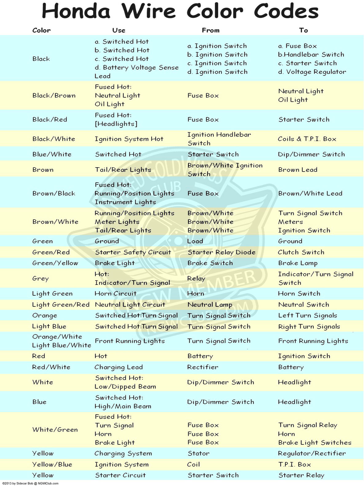
Here is the colour code as an image that you can download & print (from Sidecar Bob)
#